Create F5 LTM VIP Advanced
This workflow creates Extensive VIP with all basic objects in an F5 device and integrates with DNS - Infoblox/Bluecat for A record creation.
To run this workflow:- Go to Menu > ADC+ > AUTOMATION > Workflow Catalog > View/Run
- Click the F5 BIG-IP LTM category on the View/Run Workflows page.
-
On the popup window, hover the mouse over the Create F5 LTM VIP
Advanced workflow.
The Run and Schedule buttons are displayed.
-
Click
 .
The Request > Create F5 LTM VIP Advanced :: FormBuilder page is displayed.
.
The Request > Create F5 LTM VIP Advanced :: FormBuilder page is displayed. - Enter/select the Device Details.
Table 1. Device Details Section - Field and Description Table Field Description *Datacenter Displays the list of datacenters of the devices, which are created in the Device Inventory. Select the datacenter of a device from the drop-down option for which this request is to be created. For the devices which are created without a datacenter in the Device Inventory, select the datacenter as None. *Device Name Displays the list of devices associated with the selected datacenter. If the datacenter is selected as None, the devices that are created without datacenter details are listed. Select the desired device from the drop-down option. *Partition Partition in which objects will be created. If you want to create a new partition then click Create New Partition from the dropdown list and then provide a partition name. -
Enter/select the DNS Record Details.
Table 2. DNS Record Details Section - Field and Description Table Field Description Do you want to create A record ? The default option is No. To create A record in DNS select Yes and enter the Vendor, DNS Device, Network View, and Subnet details.
-
Enter/select the Virtual Details.
Table 3. Virtual Details Section - Field and Description Table Field Description FQDN/Application Name Enter the FQDN or application name of the virtual server. Virtual Server Type Select the virtual server type. Redirect VIP An IP forwarding virtual server accepts traffic that matches the virtual server address and forwards it to the destination IP address that is specified in the request rather than load balancing the traffic to a pool.
- No (default)
- Yes - select Yes to redirect VIP.
Destination Address Enter the destination IP address information for the virtual server. Service Port Enter a service port. -
Enter/select the Pool and Monitor Details.
Table 4. Pool and Monitor Details Section - Field and Description Table Field Description Pool You can create a pool by providing the details for the pool or select an existing pool. Select the desired option:
- Create New - this is the default option. When you select this option, you need to provide a Load Balancing Method, Address, Service Port, State, Priority Group, Pool Members, and Monitor.
- Existing - when you select this option, the Select Pool field appears to select the existing pool from the drop-down option:
Load Balancing Method The load balancing method is used to select a pool in this WideIP. The default is a round-robin. The methods are:
- round-robin - the system selects the pools sequentially.
- least-connection-node - The system passes a new connection to the node that has the least number of current connections out of all pools of which a node is a member. This method works best in environments where the servers or other equipment you are load balancing have similar capabilities. This is a dynamic load balancing method, distributing connections based on various aspects of real-time server performance analysis, such as the number of current connections per node, or the fastest node response time.
- least-connection-member - The system passes a new connection to the node that has the least number of current connections in the pool. This method works best in environments where the servers or other equipment you are load balancing have similar capabilities. This is a dynamic load balancing method, distributing connections based on various aspects of real-time server performance analysis, such as the current number of connections per node or the fastest node response time.
- ratio-member - The number of connections that each machine receives over time is proportionate to a ratio weight you define for each machine within the pool.
Address Enter the IP address of the pool. Service Port Enter a service port. State The current state of the pool members. The states are:
- user-enabled - when you select this option, the system sends traffic to this pool member regardless of the pool member's state.
- user-disabled - when this option is selected, the pool member can handle only persistent or active connections.
Priority Group A number representing the priority group for the pool members. To specify a priority, you must activate priority group usage when you create a new pool or when adding or removing pool members. When activated, the system load balances traffic according to the priority group number assigned to the pool member. Pool Members Enter the IP address of the pool member. And then click the Add button. Any number
of pool numbers can be added to the pool. After adding the pool, you can
manage them.
button. Any number
of pool numbers can be added to the pool. After adding the pool, you can
manage them.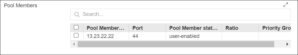
Monitor An association between a health monitor and an entire pool. Select the desired Monitor option:
- No - this option does not allow you to monitor the pool.
- Create New - select this option to create a monitor. Input the Type, Interval, Interval, Timeout, and Monitor Destination.
- Existing - select this option to choose the existing monitor option.
-
Enter/select the Persistence Details.
Table 5. Persistence Details Section - Field and Description Table Field Description Persistence This option allows you to use a pre-configured object that automatically enables persistence when you assign the profile to a virtual server.
- None
- Create New - create a new persistence by providing persistence details:
- Existing - select the existing persistence details:
Fallback Persistence It is a secondary persistence record for each connection. Select the desired following option:
- No
- Yes
-
Enter/select the Snat Pool Details.
Table 6. Snat Pool Details Section - Field and Description Table Field Description Snat Pool Select the SNAT pool for any connections using this pool. The options are:
- Auto-Mapp -This option allows you to select a translation address from the available self-IP address.
- SNAT - This option allows you to select a floating self IP as a translation address. When this option is selected, the Snat Pool field appears. Select the Snat pool from the drop-down option:
-
Enter/select the Client SSL Details.
Table 7. Client SSL Details Section - Field and Description Table Field Description Client SSL Select the Client SSL options. The options are:
- No (default)
- Create New - This option allows you to upload a new Client SSL certificate.
- Existing - This option allows you to select a Client SSL certificate from the drop-down option.
-
Enter/select the Server SSL Details.
Table 8. Server SSL Details Section - Field and Description Table Field Description Server SSL Select the Client SSL options. The options are:
- No (default)
- Create New -This option allows you to upload a new Server SSL certificate.
- Existing- This option allows you to select a Server SSL certificate from the drop-down option:
-
Enter/select the Irule Details.
Table 9. Irule Details - Field and Description Table Field Description IRule Select the IRule options. The options are:
- No (default)
- Create New -This option allows you to upload a new IRule file.
- Existing- This option allows you to select a IRule file from the drop-down option:
- Enter/select the Other profile Details.
-
Click Submit.
The Confirmation dialog box is displayed.
-
To save this form so you can edit it later, click Save Draft and then click
OK.
The form will be saved as Open request under Request > My Request.
OR
To submit the form, click OK.
The pre-validation starts automatically and reaches the Review stage. -
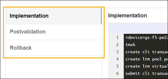
Review the input data under the implementation, rollback, and
postvalidation tabs.
-
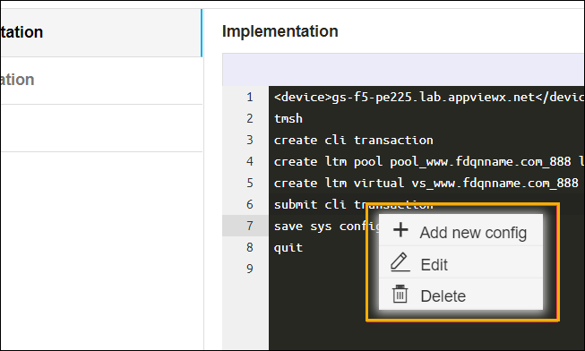
(Optional) If you need to change any data at this stage, right click, as shown in the
image below, and select the required option.
-
After the review, click Submit.
The Confirmation dialog box is displayed.
-
To continue with the workflow creation, click Ok
OR
To abort the workflow creation, click Cancel.
It takes a while to complete the post-validation.After the post-validation is successful, the workflow is created and an email triggered to all the configured email IDs.
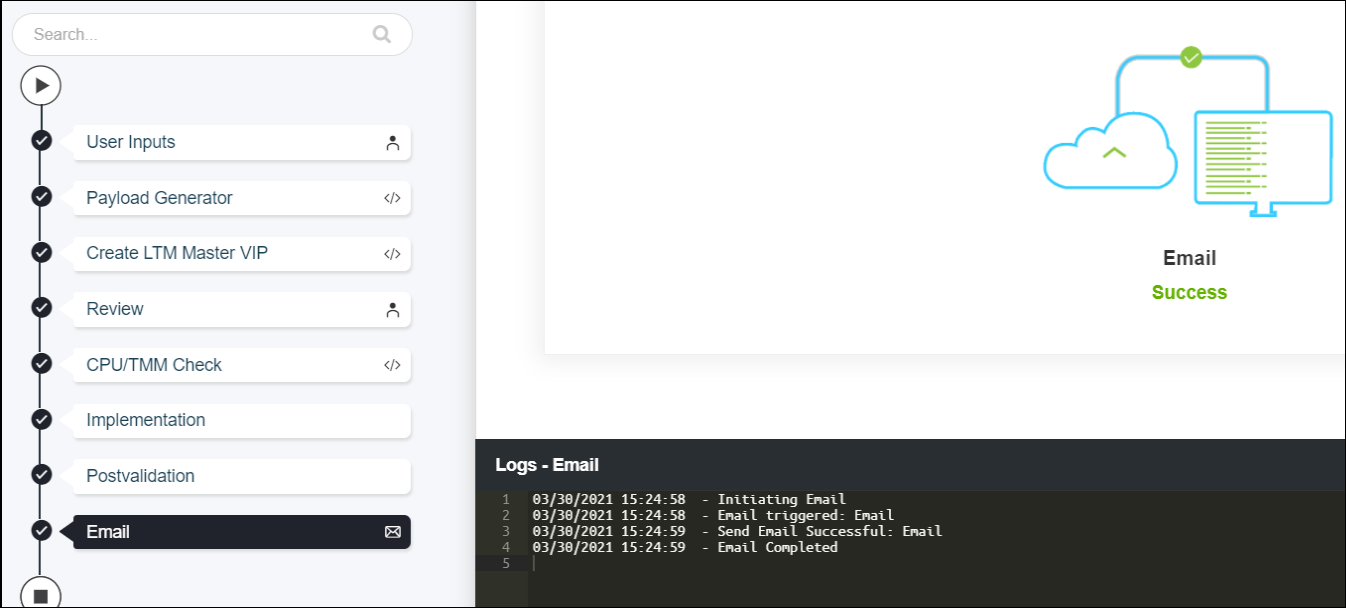 Note: The validation stages are shown in the left side of the screen. To view a validation stage, click on the respective stage.