Configuring Windows Agents in the F5 Load Balancer
Creating Nodes
A primary feature of nodes is their association with health monitors. Like pool members, nodes can be associated with health monitors as a way to determine server status. However, a health monitor for a pool member reports the status of a service running on the device, whereas a health monitor associated with a node reports status of the device itself.
Local traffic pools use nodes as target resources for load balancing. A node is an IP address or a fully-qualified domain name (FQDN) that represents a server resource that hosts applications.
To add any server you want as part of a load balancing pool, you must first create a node and assign that server as a node. After assigning the server as node, you can add the node to a pool as a pool member.
- Log on to the f5 device using your credentials.
-
On the Main tab, go to Local
Traffic > Nodes > Node
List.
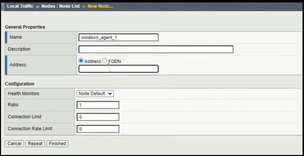
The New Node page is displayed as shown.
-
Enter the fields as described.
Field Description Name Enter a unique name. Specifies the host name of the associated IP address. Address Enter the IP address of the new node. Health Monitors Denotes the health monitor for this node By default, is it Node Default. If it is not configured, select None.
Ratio Denotes a weighted value to assign to the node If the nodes that belong to the same cluster all have the same capacity, enter 1 as the ratio value for each node.
Connection Limit Denotes the maximum number of connections that this node can handle - Click Finished.
-
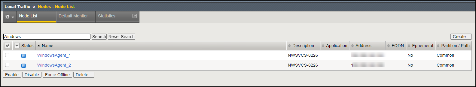
To create additional nodes, repeat steps 1 to 4.
The new nodes are displayed in the Node List.
Creating Pools
- Decide the IP addresses or FQDNs for the servers that you want to include in your server pool.
- If your system is using DHCP, make sure your DNS servers are not configured for round robin DNS resolutions; instead, they must be configured to return all available IP addresses in a resolution.
A pool is a logical set of devices, such as web servers, that you group together to receive and process traffic. Instead of sending client traffic to the destination IP address specified in the client request, the BIG-IP® system sends the request to any of the nodes that are members of that pool.
A pool consists of pool members. A pool member is a logical object that represents a physical node on the network. Once you have assigned a pool to a virtual server, the BIG-IP system directs traffic coming into the virtual server to a member of that pool. An individual pool member can belong to one or multiple pools, depending on how you want to manage your network traffic.
You can create three types of pools on the system: server pools, gateway pools, and clone pools.
- On the Main tab, go to Local Traffic > Pools > Pool List.
-
Enter the fields as described.
Field Description Name Enter a unique name for the pool. Description [Optional] Enter additional details related to the pool being created. Health Monitors Select a monitor from the Available list and move it to the Active list. Load Balancing Method Select how you want the system to distribute traffic to members of this pool. By default, it is Round Robin.
New Members - Select Node List and select the node you created from the dropdown list.
- Enter the Service Port number.
- Click Add.
The node is populated in the table.
- To add multiple nodes, repeat steps a to c.
- Click Finished.
-
To create new pools, repeat steps 1 to 3 for each pool.
The added pools are listed as shown in the image below.
 Note: Each pool or pool member is distinguished by shape and color using icons. For example:
- Green indicates that the pool member is up.
- Red indicates that the pool member is down.
- Black indicates that user intervention is required.
Importing SSL Certificates and Creating Client/Server SSL Profiles
- Self-signed certificate: A self-signed certificate is signed by its own private key. BIG-IP software includes a self-signed SSL certificate named default, which the SSL profile can use to terminate SSL traffic. You can also use the Configuration utility pages to renew existing self-signed certificates or create additional self-signed certificates.
- CA certificate: A CA certificate is signed by a CA's private key. Using a CA certificate allows you to replace the self-signed certificate on each BIG-IP system with a trusted CA certificate, which is a certificate signed by a third party. Authenticating BIG-IP systems using trusted CA certificates is more secure than using self-signed certificates. The Configuration utility provides a set of certificate management pages that allow you to create certificate signing requests (CSRs). The requests can then be sent to the CA for a signature.
-
On the Main tab, go to SSL Orchestrator >
Certificates and Keys and click
Import.
The SSL Certificate/Key Source page is displayed.
-
Enter the inputs as described.
Field Description Import Type From the dropdown list, select PKCS 12 (IIS). Certificate Name Click New and enter a unique name. Certificate Source Browse to upload the file. Password Enter a password. Key Security From the dropdown list, select the required value. The imported certificate is displayed in the Traffic Certificate Management list.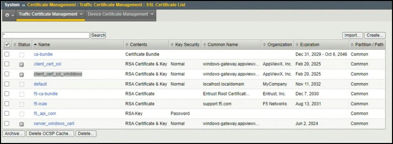
-
Go to SSL Orchestrator >
Profiles > Client SSL and
click Create.
- Enter a unique name.
- In the Client Authentication section, select Custom.
- From the Trusted Certificate Authorities dropdown list, select the certificate you imported from the preceding step.
- From the Advertised Certificate Authorities dropdown list, select the certificate you imported from the preceding step.
-
Click Finished.
The Client SSL profile is created.
- Repeat the aforesaid steps to create the Server SSL profile.
Creating Virtual Lists
When you create a virtual server, you specify a destination IP address and service port. All other settings on the virtual server have default values. You can change the default values of any settings to suit your needs.
A virtual server is one of the most important components of any BIG-IP® system configuration. A virtual server is a traffic-management object on the BIG-IP system that is represented by a virtual IP address and a service, such as 192.168.20.10:80. When clients on an external network send application traffic to virtual server, the virtual server listens for that traffic and, through destination address translation, directs the traffic according to the way that you configured the settings on the virtual server. A primary purpose of a virtual server is to distribute traffic across a pool of servers that you specify in the virtual server configuration.
To customize the way that the BIG-IP system processes various types of traffic, you can assign profiles to a virtual server. For example, through profile assignment, a virtual server can enable compression on HTTP request data as it passes through the BIG-IP system, or decrypt and re-encrypt SSL connections and verify SSL certificates. For each type of traffic, such as TCP, UDP, HTTP, SSL, SIP, and FTP, you can assign a custom profile to the virtual server or use the default profile.
When you create a virtual server, you specify the pool or pools that you want to use as the destination for any traffic coming from that virtual server. You also configure its general properties, profiles, SNATs, and other resources you want to assign to it, such as iRules or session persistence types.
-
On the Main tab, go to Local Traffic >
Virtual Servers > Virtual Server
List.
-
Click Finished.
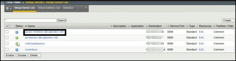
The newly created virtual server is displayed in the Virtual Server List with a blue icon. The icon turns green once the validation is completed.
- Create a DNS record and expose the virtual server publicly. Once done, you can configure it in your application.